Professional Fuselage Tailboom Repair by Dennis L Harvey
This article is adapted from the article which appeared in the July 2022 issue of Model Aviation.
I have the dubious reputation of being a wizard at carbon fiber repair. I say dubious because that also means I’ve made countless repairs because I’ve crashed so many times trying to get up the learning curve of F3J spot landings. But I can also claim I’ve had decades of experience with composites during my career and with other hobbies, including boating. This article will share some of the tricks to making a virtual invisible repair of a fuselage broken in two.
For this article, I am repairing the Pitbull of a friend where the boom was broken clean in half but the push rods at first appeared to be okay. Later, they were removed and replaced because of delamination. The Pitbull has a particularly thick boom layup but the techniques in this article also apply to the thinner layups in F5J fuselages.
Sleeving the Break Area
Figure 1 shows the break with the damaged push rods in place. This type of break is very common on hard landings, particularly when the sailplane spins around. Below the fuselage is the sleeve which we will make.
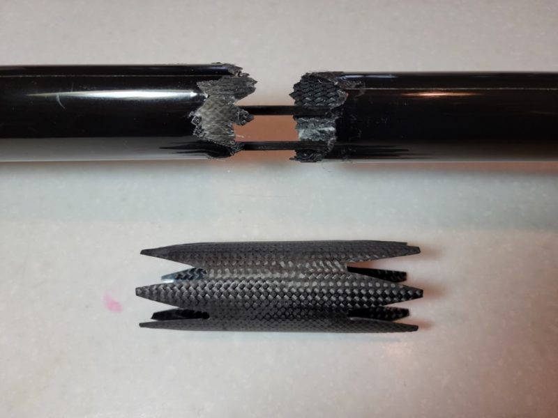
Figure 1. Damaged boom and the sleeve to be made.
The first thing you notice about the sleeve (which will be installed inside the broken fuselage) is that both ends have a six-point crown shape. The purpose of this is to transition the boom stiffness so that on the next hard landing, you’re not breaking the boom again at the edge of the sleeve. This is highly likely without this transitional shape. The shape is easy to cut with a Dremel tool and a diamond cutting wheel.
Please note that the uncrowned length of the sleeve should be about 20 mm greater on each side of the break. The crown points should be maybe 30 mm. Use these measurements and your break to determine how long your sleave should be in the next step.
Molding your sleeve
Figure 2 shows the sleeve ready to be molded. There is a lot to observe in this photo.
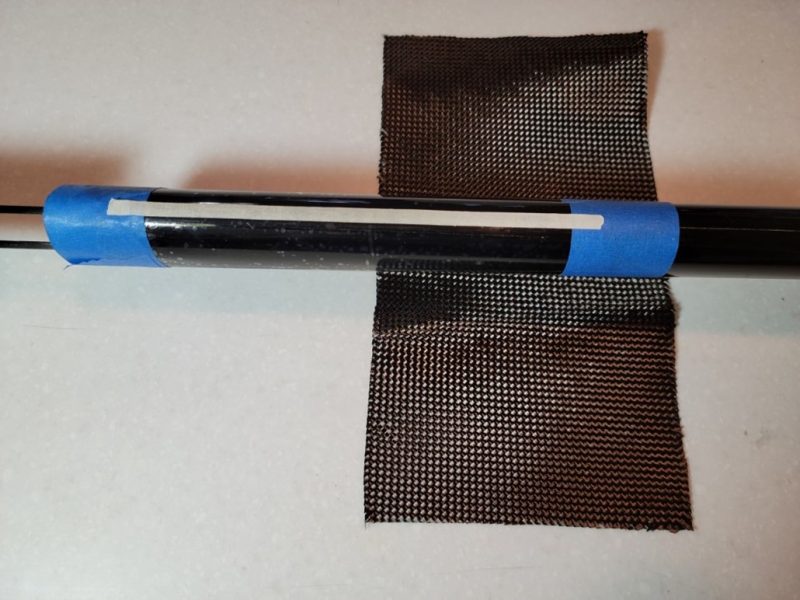
Figure 2. Preparation to mold the sleeve
The first thing you must do is determine the dimensions of the carbon fiber cloth you will use to mold the sleeve. The parameters for determining the length of the sleeve were given in the last section. In this Pitbull example, the sleeve needed to be 110 mm so considering molded edge scrap, the carbon fiber cloth is 130 mm wide.
I want to highly recommend that the piece of carbon fiber cloth you use be biased ply, that is, the fiber orientation is oriented 45° to the edges. All fuselages are molded this way because the orientation results in a strength and stiffness about 40% greater than if the strands were oriented along the axis and circumference of the boom.
What is the other dimension of the cloth? You will be molding the sleeve on the outside of the tail boom aft of the break such that it will eventually slide into the larger section of the fuselage where the break occurred. Pick your place on the fuselage where you are going to mold the sleeve and carefully tape over the area with clear packaging tape. Epoxy will not adhere to this tape so you will not need a release agent. Make sure the tape overlaps so that no fuselage is exposed. I taped about 200 mm of length and used 1.5 inch wide masking tape to protect the edges of my workspace.
Next measure the circumference of the fuselage where you will be molding. You must determine how many layers for the sleeve. I use calipers to measure the thickness of the fuselage at the break and compare it to the thickness of the CF cloth I will use. In this example, I need three layers of 5.7 oz/sq yd carbon fiber cloth which worked out to a swatch 320 mm in length.
The last thing to notice in Figure 2 is the thin strip of lighter colored masking tape on the top of the work area. Once the raw sleeve is solidly cured, I used a Dremel tool with a diamond wheel cutter and carefully cut the part along the top until the lighter color tape is just visible. Pry the part apart and remove. Next use the Dremel with the diamond wheel to cut the sleeve to the crown shape shown in Figure 1.
I exclusively use West Systems 105 epoxy with 206 slow cure catalyst.
Installing the sleeve
Once the sleeve is cut to shape, try to fit it into the forward section of the fuselage. You may have to grind down the inside of the seam where the fuselage halves join. Also, you may have to use the diamond wheel to increase the size of the sleeve cut line so it fits snugly into the forward section of the fuselage.
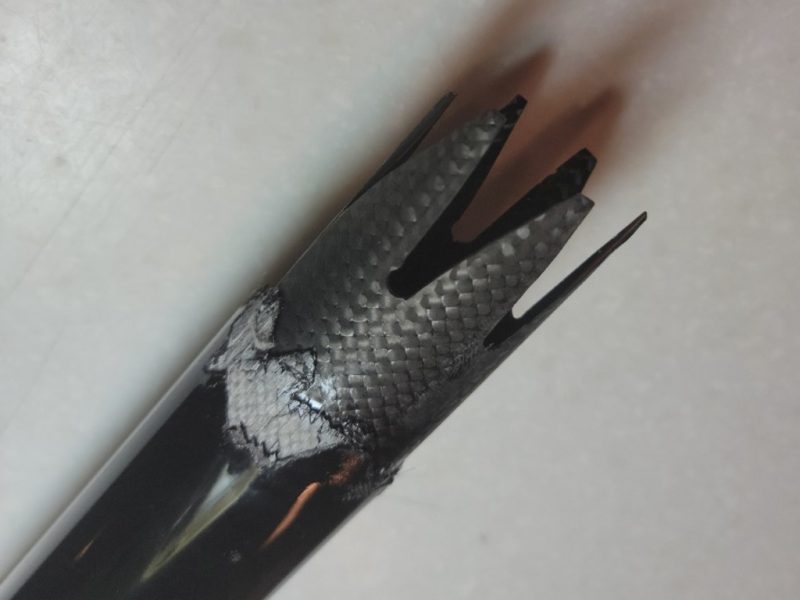
Figure 3. Sleeve inserted in the forward section of fuselage.
Figure 3 shows the sleeve inserted into the forward fuselage such that half the uncrowned section length is concealed and half remains ready for the tail section. Make sure the sleeve is square by using a straight edge along the fuselage to make sure it’s not cocked. Set aside and let this hard cure.
Final alignment and sleeve bonding
Figure 4 shows the final alignment of the Pitbull. Some things to notice. Once the epoxy was slathered on the sleeve and inserted into the tail of the fuselage, an aluminum splint was used to assure there was no offset in the boom surfaces and to assure alignment in the pitch axis. The yaw axis alignment was done by visually sighting along the fuselage seams. The roll axis is tricky. You may have to twist the fore and aft fuselage sections to assure the tail is aligned with the wings.
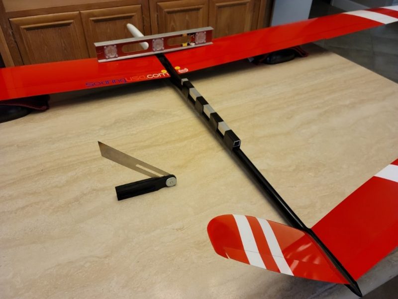
Figure 4. Final alignment and sleeve bonding
Preparing the boom for a splice
The boom now has a sleeve bonded to the inside, which can support the loads. By splicing the boom material on either side of the break, the repair is almost doubled in strength and will also allow for a resilient finish.
Figure 5 shows how the boom material is ground to a concave shape in anticipation of adding layers of carbon fiber and epoxy. Look closely on the left side of the remaining carbon fiber on the boom to see the concave shape. You should grind down till the sleave is visible and the break is ground away.
How wide should the concave area be? Usually, you want to set your guide masking tape 15 mm past the break. In the Pitbull example, the break fluctuated about 20 mm so the span of the concave area was 50 mm.
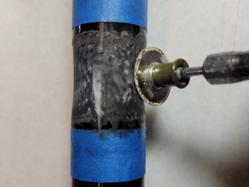
Figure 5. Shaping the concave splice area on the boom.
Do not worry about making the raw carbon fiber area pretty. Leave the surface rough to assure good adhesion.
Molding the splice
Put fresh masking tape on either side of the concave area and make sure it is only one layer thick.
Figure 6 shows the carbon fiber just covering the edge of the masking tape. You have to decide how many layers of carbon fiber are necessary. If you use the same weave CF cloth as you did for the boom, it should be the same number of wraps. It is better to err on the side of too many carbon fiber layers than not enough since you will be sanding them down and you don’t want to have to fill in any valleys.
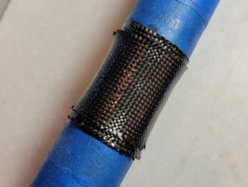
Figure 6. Molding the splice with one layer of masking tape on the perimeter.
In the Pitbull example, I changed from using 5.7 oz/sq yd cloth to a finer 3.75 oz/sq yd so instead of 3 layers, I needed 4. When you apply this carbon fiber epoxy mix, make sure you work out any air pockets or voids to make the rest of the job goes easier.
Roughing the surface shape
Once the carbon fiber is hard cured, use a Dremel sanding disk and/or a coarse sanding block to take the carbon fiber to the thickness of the masking tape perimeter. You will know you are there when the black carbon fiber disappears from on top of the masking tape but the masking tape is still intact.
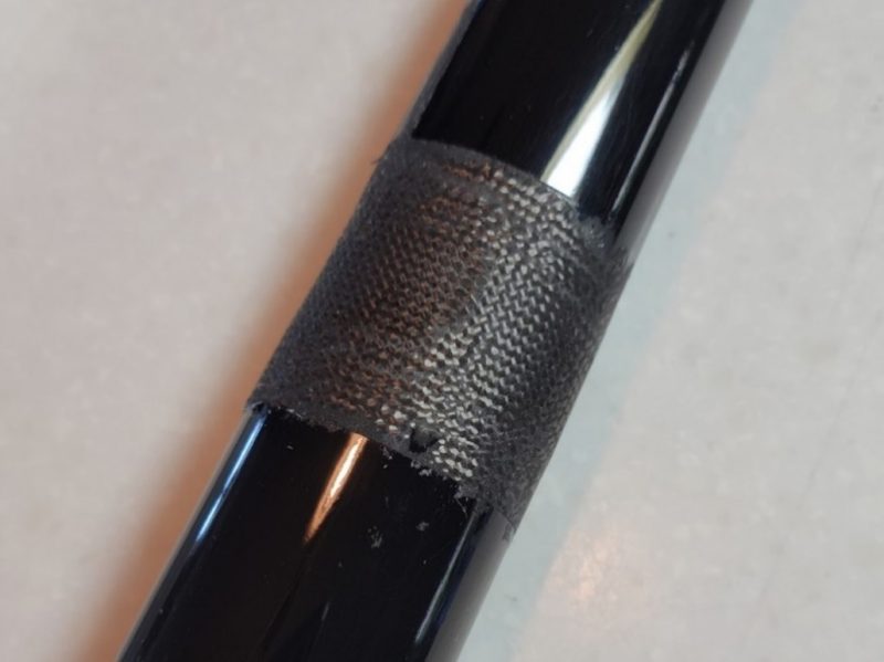
Figure 7. Rough sanded down to the masking tape perimeter (masking tape removed).
Figure 7 shows the splice rough shaped to within the thickness of the masking tape on the perimeter. The masking tape has been removed, ready for the next step.
Fine sanding, ready for gel or clear coating
Figure 8 shows the splice area block sanded to final shape. Using a sanding block helps you make sure you have worked out any waviness. You can ding the surrounding area and not worry because there is still a sleave under your work. For the best results, I try to get the final sanding done with 1200 grit wet/dry paper.
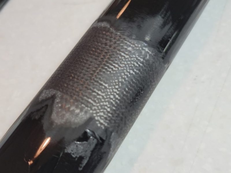
Figure 8. Fine sanding ready for gel or clear coat.
Final finish coat
In the case of the Pitbull, the fuselage is black gel coated. I chose to apply a few coats of epoxy with black pigment specifically formulated for epoxy. The final coat (it took three) made the repair area look flawless.
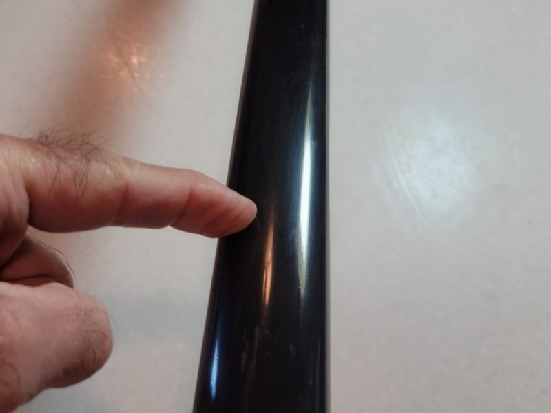
Figure 9. The finished repair.
Figure 9 shows the finished repair which has been buffed out with automotive polishing compound. My finger is exactly over the point at which the break had occurred. Notice that the reflection of light on the surface shows that there is no waviness or surface distortion in the repair.
For a clear epoxy fuselage that shows off the carbon fiber structure underneath (no gel coat), using regular epoxy for the final coat can give you stunning results. For the last coat, after prepping the surface with a 1200 grit sanding, I lightly smear epoxy over the work area and wipe almost all the epoxy off except for a light film that is too shallow to have brush marks. This usually lays right down to a glossy finish. It’s critical that the epoxy and catalyst are insanely mixed to assure curing. No post processing is necessary though you could buff it out.
There you have it. Try this yourself and when you are finished, show off your masterful repair to your flying friends.
